Forces Acting on the Motorcycle’s Centers of Gravity (part 1)
The Science
A quick recap the law of inertia
“A body at rest will stay at rest until, acted upon by an outside force".
“A body in motion will tend to keep in motion, in a straight line, unless acted upon by an outside force.”
There is a misconception about a commonly used term used in motorcycle operation it is “Centrifugal Force”. Arguably, in the real world there is no such thing as centrifugal force, it is, in fact, just straight line inertia. There is no mention or definition of a centrifugal force in the strict laws of physics, other than “An Apparent Force", acting outward on the object traveling in a circle”
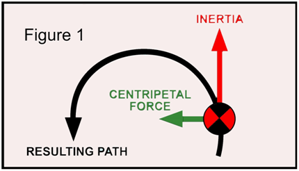
(Figure 1)There are, however, “Centripetal Forces”. These are the forces acting on a body and cause the body in motion to change direction and follow a curvilinear path.
We can use the famous example of a spinning ball on a string. The movement of the ball causes an inertial force (body in motion). This inertia will try to keep the ball moving in a straight path (RED LINE).
A “Centripetal Force”, (Green Arrow) is generated by the string. This is the force pulling the ball inward. The result is the ball now travels in a curvilinear path. When referring to motorcycle cornering dynamics, we can use the terms, “Inertia” or “Cornering Forces” interchangeably and the tires, like the string, generate the "Centripetal Force".
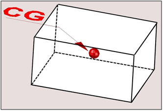
 Every object that has mass will have a “Center of Mass” or commonly called “Center of Gravity” (CG). For example, if the cube, shown here, is symmetrical in all dimensions, then the CG will in the center of the cube.
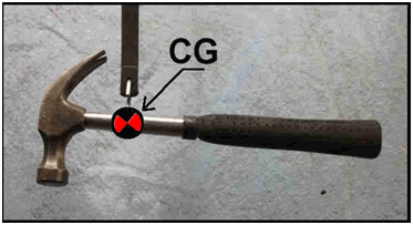
An odd, shaped object is heavier on one end. The CG will not be in the middle of the object, such as the hammer shown here. With the head of the hammer being heavier than the handle the CG will be closer to the head.
(Figure 2) Another dynamic we should be familiar with is “Force Vectors”. This shows an object in three different situations.
(Figure 2A) represents a stationary object (I.E., a body at rest). The only force acting on the object is gravity (Red Arrows).
(Figure 2B) we see an object that has a second force applied. This will represent the force if inertia (Blue Arrows).
(Figure 2C) The two forces acting on the object will combine. This shows the resulting “Force Vector” (Green Arrow). This is the direction that the combined forces of gravity and inertial will try to move the object.

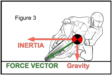
(Figure 3) We can now look at this in a little more detail. We will look at a motorcycle in a stable lean angle in mid-turn. You can see the gravity acting on the CG is trying to pull the motorcycle down. The inertia, from cornering, is trying to pull the motorcycle back up or at least stop the fall. The final result is a combination of inertial force and gravity will generate a "Force Vector".
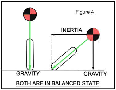
(Figure 4) The important point to learn here is, that anytime the motorcycle is at a stable and balanced state, either straight up or leaned over, the Force Vector is always pointing directly from the CG to the tire contact patch.
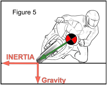
 (Figure 5) It is this Force Vector that transfers the forces acting on the CG to the tire contact patch. These are the forces; the tire contact patch feels. The pull of gravity gives the traction, and the inertia or cornering forces use it up.
Applied Torque
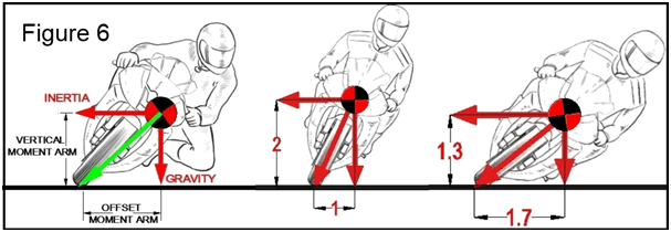
(Figure 6) An alternate way of looking at these forces, of gravity and inertia, is to think if them as two opposing torques on the chassis.
Using the tire contact point as a fulcrum point, the distance from tire contact patch to a point directly below the CG is like a torque arm. I refer to it as the “Horizontal, “Offset Moment Arm” or “Torque Arm ”. The resulting torque, generated, is trying to pull the bike down. The longer the torque arm is, the higher the resulting torque, pulling the CG downward, will be.
As seen here, the further the bike is leaned over, from higher cornering speed, the longer the offset moment arm gets, thus developing more torque pulling the bike down.
Besides the horizontal Offset arm there is a “Vertical Moment Arm”. This “moment arm” is an imaginary lever extending from the tire contact patch, vertically to a point directly horizontal from the CG. The inertial forces will work on this arm and develop a torque to straighten or hold the bike up.
You can also notice as the bike leans further over the shorter the Vertical torque arm will be. The result is the bike must be going faster or on a smaller radius to keep the applied torques equal.
In conclusion, to maintain a stable and balanced lean angle, both torques on the chassis still must be equal, to each other, no matter the cornering speed. If they are not equal then the bike will have to change its lean angle either up or down.
Body position and how it relates to the movement of the CGs and torques on the chassis will be discussed in the tutorial “BP & How it Works”.